AR-716E
![]() Only when AR-716E (Multi-Door Networking Controller) connected with PC then could entry 701parameters.
Only when AR-716E (Multi-Door Networking Controller) connected with PC then could entry 701parameters.
Read From Controller
There are two ways to open the 701E Parameter window: Setting – Controller Parameters and ![]() .
.
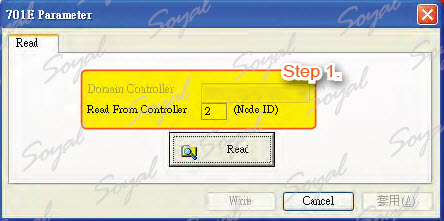 Step 1.There is filled in AR-716E node ID to get in 716E parameter for others setting.
701E Parameters
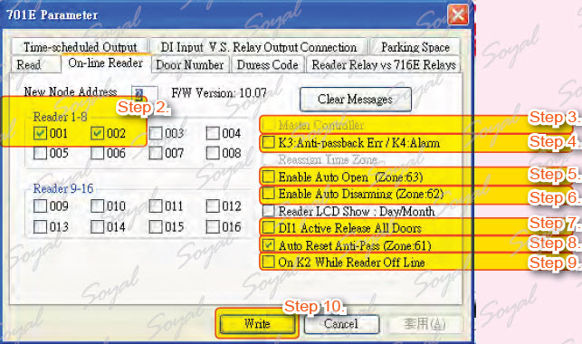 Step 2. There are two channels of AR-716E, each channel could connected with 8 sets of readers. AR-721H is the first access controller and node ID is 001, AR-727H is the second access controller and node ID is 002.
Step 3. If there are many networking access controllers, important access controller can be set for master reader of network.
Step 4. Select OnK3 is used in users violation of anti-pass back or OnK4 is used in alarm output.
Step 5. Enable auto open time zone, this function be set in zone 63 .
Step 6. Enable auto enter arming mode, this function be set in zone 62 .
Step 7. DI1 will be responsible for receiving the emergency message and open all the doors.
Step 8. Reset is used when the user violations and emergencies, reset function of anti- pass back, this function be set in zone 61 .
Step 9. K2 will be responsible for receiving the disconnected message message and sending messages to administrator.
Step 10. Press Write button to save all settings.
Door Number
The number corresponds to location to help user identify access record and area. Node ID corresponds to access controller to help PC identify access controller and data.
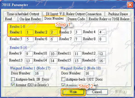 Step 1. Select Door Number tag and enter of the controller corresponding the door number, reader 1’s door number is 1, reader 2’s door number is 2.
Step 2. Press Write button to save all settings.
NOTE
There are two WG channels of AR-716E, each channel could connected with 1 WG access reader.
The first WG reader node ID is 17, the second WG reader node ID is 18. Here you can set the following functions:
1. Anti-pass back
2. DI3 and DI4 has sensor function.
Duress Code
If you meet abnormal person to threaten open the door, for assistance you can input duress code and send message to control center.
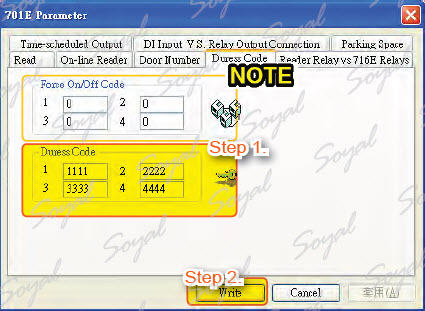 Step 1. Enter up to 4 sets duress code, for example:1111, 2222, 3333, 4444.
Step 2. Press Write button to save all settings.
NOTE
Setting duress code in the 701E Parameter is the main duress code.
※ Force On/Off Code be used to control relay.
Reader Relay and 716E Relay
There are 4 relay of AR-716E, K1 to K4, which action time could be set here. The extensive relay board, EXK1 to EX-K8, which action time also could be set.
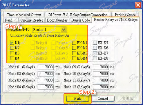 Step 1. Select the node ID and name of relay. Here, we will synchronize the node 001 with K-1 and synchronize the node 002 with K-2.
Step 2. Press Write button to save all settings.
Time-Scheduled Output
There is a time-scheduled output of AR-716E for using, setting relay output, specify the weekday, time. General be used in office and auto managemet.
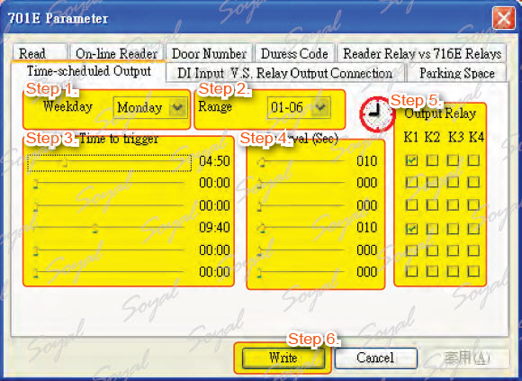 Step 1. Select Monday for time-scheduled.
Step 2. Determine to display how much data, once can be displayed 6 document data.
Step 3. Determine alarm time, for example: 04:50am and 09:40am.
Step 4. Select the alarm duration: 10 sec.
Step 5. Select relay for alarm output.
Step 6. Press Write button to save all settings.
DI Input and Relay Output Connection
Using the AR-716E’s DI control relay and request to exit (RTE).
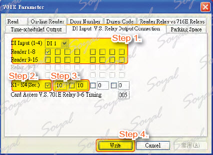 Step 1. Selection the number of DI and the corresponding access controller. For example: DI1 corresponding node ID is node ID 1 (AR-721H), DI2 corresponding node ID is node ID 2 (AR-727H).
Step 2. Selection the number of DI and the corresponding relay. For example: DI1 corresponding relay is K1, DI2 corresponding relay is K2.
Step 3. Input lock relay time: K1 and K2 lock relay time are 10 seconds.
Step 4. Press Write button to save all settings.
NOTE
If you do not perform Step 2, lock relay time will be by the same as lock relay time on access controller.
Parking Space
This application for parking lots, which could monitor the parking space status and message output to designate devices.
| ย้อนกลับ | กลับสู่เมนูหลัก | ถัดไป |